Skip to content
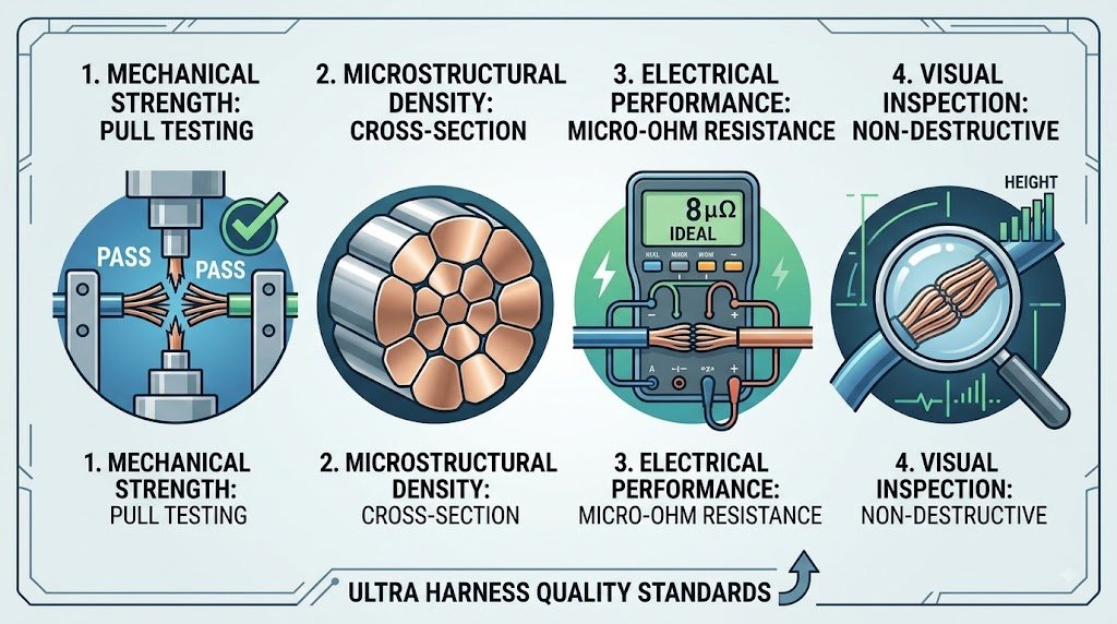
In the EV and automotive manufacturing industries, wire harness assembly requires uncompromising joint integrity. Unlike traditional crimping or soldering, ultrasonic metal welding creates a solid-state molecular bond. However, to guarantee long-term performance under harsh vehicle operating conditions, establishing a rigorous quality evaluation standard is essential.
This article outlines the four critical metrics and testing methods used by leading tier-1 suppliers to inspect and validate ultrasonic wire harness welds.
1. Mechanical Strength: Pull Force Testing (Destructive Test)
The pull-force test (tensile strength test) is the most common destructive method to verify the mechanical bond of a welded splice or terminal.
- Testing Method: The welded harness sample is clamped into a calibrated tensile testing machine. Force is applied linearly until the joint breaks or the wire strands snap.
- Acceptance Criteria: The weld joint must meet or exceed relevant automotive standards (such as USCAR-38 or IPC/WHMA-A-620).
- Failure Mode Analysis:
- Wire Break (Ideal): The individual copper or aluminum strands break away from the weld zone. This indicates that the molecular bond is stronger than the parent wire itself.
- Joint Separation (Defect): The weld interface pulls apart. This signifies under-welding, insufficient energy, or contaminated wire surfaces.
2. Microstructural Density: Cross-Sectional Analysis (C-S Analysis)
While pull testing measures strength, cross-sectional analysis evaluates the internal compaction and molecular intermixing of the strand bundle.
- Testing Method: The welded node is resin-encapsulated, cut, polished, and etched before being examined under an optical microscope or Scanning Electron Microscope (SEM).
- Key Evaluation Metrics:
- Compaction Rate: A high-quality weld should achieve a compaction density between 85% and 95%, leaving minimal internal voids or air pockets.
- Inter-strand Bonding: Individual strand boundaries should be deformed into polygonal shapes, blending smoothly into a homogeneous metal mass without visible gaps.
- Micro-Cracks: The cross-section must be completely free of micro-cracks or severe material embrittlement caused by excessive vibration amplitude.
3. Electrical Performance: Micro-Ohm Resistance Testing
Because wire harnesses carry high currents (especially in EV high-voltage systems), any extra resistance at the weld joint leads to localized heat buildup and energy loss.
- Testing Method: A 4-wire Kelvin resistance meter is used to measure the electrical resistance across the welded joint in micro-ohms (μΩ).
- Standard Requirement: The electrical resistance across the ultrasonic weld zone should be virtually equal to—or slightly lower than—an equivalent length of unbroken parent wire.
- Why Ultrasonic Excels: Because no solder or third-party flux material is introduced, the joint avoids galvanic corrosion and extra resistivity, ensuring consistent electrical conductivity over time.
4. Visual Inspection & Dimensional Tolerances (Non-Destructive)
Visual and dimensional checks serve as the first line of defense during inline production monitoring.
- Loose Strands (Flyaway Wires): All strands must be fully contained within the weld nugget. No single strand should bypass the compaction zone.
- Burrs & Over-flashing: Excessive flash along the edges indicates over-pressure or worn horn/anvil tooling.
- Color & Discoloration: The copper or aluminum should retain its natural metallic luster. Surface darkening or oxidation indicates extreme friction heat or parameter misconfiguration.
- Height & Width Tolerances: Ultrasonic welding machines equipped with dynamic height monitoring ensure that every weld falls within preset ±mm height limits.
Summary Checklist for Quality Assurance
| Inspection Item | Testing Method | Key Parameter / Target Value | Primary Failure Risk |
|---|---|---|---|
| Mechanical Strength | Pull-force Gauge | Meets USCAR / IPC standards; Strand break | Under-welding / Low tension |
| Compaction Density | Metallographic C-S | 85% – 95% Density; Zero internal void | Loose bundle / High resistance |
| Electrical Resistance | 4-Wire Kelvin Meter | Resistance ≈ Unbroken parent wire | Overheating / Power loss |
| Dimensions & Optics | Height Sensor & Camera | Precise width/height; No loose strands | Short circuits / Tooling wear |
Elevating Your Harness Quality with Bonne Ultrasonic Solutions
Ensuring consistent weld quality requires a combination of precise machine control, durable tooling, and dynamic parameter monitoring. Bonne Ultrasonic Technology designs wire harness welders with built-in height, energy, and time control, helping manufacturers achieve zero-defect production for both low-voltage and high-voltage EV applications.
Need sample testing or assistance with your wire harness welding parameters? Contact our engineering team today to request a comprehensive weld analysis report.