Skip to content
Ultrasonic Metal Welding · Engineering Guidance
In ultrasonic metal welding, the difference between a flawless joint and a field rejection often comes down to three numbers. After more than a decade of process engineering for automotive wire harness applications—from copper terminal splices to aluminum bus bars—our team has mapped exactly how amplitude, pressure, and weld time interact. This guide explains the physics, reveals the tradeoffs most equipment catalogs omit, and shows how our machines give process engineers precise, repeatable control over all three variables simultaneously.
✦ ISO 9001:2015 & IATF 16949 Certified Manufacturer ✦ 20 kHz – 40 kHz Frequency Range ✦ Tier 1 Automotive Supply Chain Experience
Why These Three Parameters Govern Weld Quality
Ultrasonic metal welding joins conductors without heat from an external source. A piezoelectric transducer converts electrical energy into high-frequency mechanical vibration—typically 20 kHz or 35 kHz—which the sonotrode transmits laterally across the weld interface. Plastic deformation and frictional heating at that interface break up surface oxides and create solid-state metallurgical bonds in milliseconds.
The process window is narrow. Too little energy and the bond is incomplete; too much and the copper strands erode, the terminal deforms, or intermetallic phases form in aluminum-to-copper joints. That narrow window is controlled entirely by three variables:
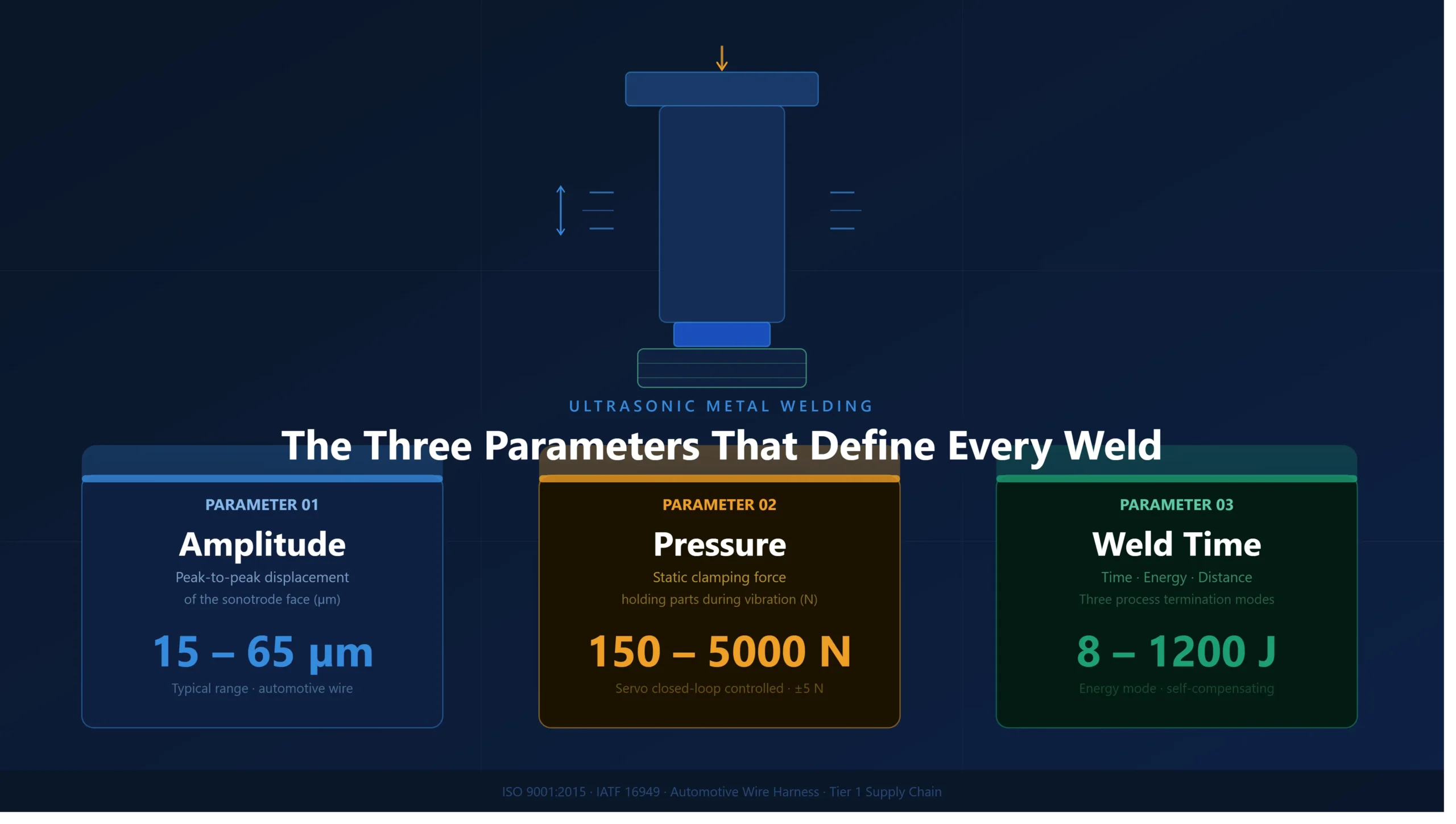
- Amplitude — how far the sonotrode face moves on each oscillation cycle
- Pressure (Clamping Force) — the static load holding the parts together during vibration
- Weld Time (or Energy / Distance) — how long vibration is applied, or the total energy delivered
Each variable is independent at the control panel but deeply coupled in the physics. The sections below treat them individually before explaining how to balance all three.
Parameter 1 — Amplitude: The Engine of Plastic Deformation
What amplitude actually means
Amplitude is the peak-to-peak displacement of the sonotrode face, measured in micrometers (µm). A 20 kHz machine oscillating at 30 µm amplitude means the sonotrode tip travels 30 µm forward and 30 µm back—60 µm total excursion—20,000 times per second. The velocity at peak displacement approaches 1.9 m/s. That velocity is what drives the micro-slip, frictional softening, and inter-diffusion at the weld interface.
The physics most suppliers leave out
Amplitude determines the shear strain rate at the interface. Higher amplitude generates more frictional heat per cycle, which softens the material faster. However, amplitude also controls lateral sonotrode force on the wire strands. In automotive copper splices—where individual strand diameters range from 0.08 mm to 0.35 mm—excessive amplitude causes strand breakage at the outer edges of the weld node, a failure mode that does not always appear in cross-section pull tests but surfaces as flex-fatigue cracking in vibration qualification.
⚠️ Common procurement mistake: Buyers compare equipment by maximum amplitude spec. A machine capable of 80 µm is not better than one limited to 60 µm. What matters is how precisely amplitude can be maintained under load—that is, whether the generator uses closed-loop frequency tracking to hold the sonotrode at resonance as tool wear changes the system’s natural frequency.
Amplitude by material and application
| Application | Typical Amplitude Range | Key Constraint |
|---|---|---|
| Copper wire splice (≤4 mm²) | 20 – 35 µm | Strand breakage limit |
| Copper wire splice (4 – 50 mm²) | 30 – 55 µm | Sonotrode contact pressure distribution |
| Aluminum bus bar (1–3 mm thick) | 40 – 65 µm | Oxide layer thickness; work hardening |
| Copper-to-terminal (brass/tin-plated) | 25 – 40 µm | Terminal deformation tolerance |
| Lithium cell tab welding (Al/Cu) | 15 – 30 µm | Tab tear strength; cell housing clearance |
How our equipment handles amplitude
Our generators incorporate digital PLL (Phase-Locked Loop) frequency control that continuously adjusts drive frequency to maintain the sonotrode at its mechanical resonance point. Amplitude deviation under load is held to ±1 µm across production shifts. Booster ratios are field-changeable (1:1 / 1:1.5 / 1:2) so process engineers can recenter the amplitude range without replacing the transducer stack—a significant advantage when a single machine handles multiple wire cross-sections across model year changeovers.
Parameter 2 — Pressure (Clamping Force): The Variable That Controls Weld Geometry
Static force vs. dynamic contact
In ultrasonic welding literature, “pressure” refers to the pneumatic or servo-driven static clamping force applied perpendicular to the sonotrode face—the force that holds the wire bundle against the anvil during vibration. It should not be confused with the acoustic radiation pressure of the vibration itself, which acts in the lateral direction.
Clamping force determines two things simultaneously: the contact geometry of the bundle (how flat the weld node cross-section becomes) and the coupling efficiency between the sonotrode face and the top layer of strands. Too little force and the sonotrode skips—vibration energy is reflected rather than transmitted, producing a “rattling” weld with poor inter-strand fusion. Too much force and the strands are crushed before vibration begins, increasing contact area so much that the sonotrode cannot sustain oscillation amplitude—a condition called “overloading” that the generator’s power limiter will flag, but that inexperienced operators often misinterpret as a component defect.
Pressure–amplitude coupling: the interaction buyers rarely see tested
Amplitude and pressure are inversely coupled in their effect on weld temperature. Reducing pressure while holding amplitude constant produces more localized heating because the contact area shrinks and the energy density at the weld interface rises. This is not always intuitive to procurement teams evaluating equipment from spec sheets: a machine with lower maximum force specification is not necessarily less capable for fine-wire work.
💡 Process insight for harness engineers: For mixed cross-section splices—a common scenario in automotive grounding rings where multiple wire gauges join a single terminal—the correct strategy is to optimize pressure for the smallest-diameter strands (to avoid strand breakage) and compensate for energy delivery with amplitude and time. Our machines allow dual-zone pressure profiling: a high initial force to position the bundle, followed by a programmed reduction to the weld set-point before vibration starts.
Servo-driven vs. pneumatic force control
The industry is moving away from fixed-orifice pneumatic cylinders toward servo-actuated weld heads. The reason is reproducibility: pneumatic force varies with shop air pressure fluctuations (±5–15% across a production shift is common), and soft-start ramp rates are difficult to control. Servo-driven heads deliver programmable force profiles, real-time force feedback, and closed-loop corrections at cycle frequencies fast enough to compensate for bundle height variation within a single weld cycle.
Our servo weld systems log actual clamping force at 1 ms resolution for every weld cycle. This data is available via OPC-UA or Ethernet/IP for integration into MES systems—a requirement increasingly specified by Tier 1 customers running statistical process control to IATF 16949.
Parameter 3 — Weld Time, Energy, and Distance: Choosing the Right Process Control Mode
Three ways to terminate a weld cycle
Unlike resistance welding, where current is the primary control variable, ultrasonic welding offers three distinct termination modes. Understanding when to use each is one of the clearest differentiators between experienced and inexperienced process engineers.
Time Mode
Vibration runs for a fixed duration (typically 100–800 ms for wire splices). Simple to program, but sensitive to input variation: if a bundle arrives slightly dry versus slightly contaminated, the actual energy deposited varies with no corrective action. Use time mode only when incoming material variation is tightly controlled—for example, in a cell that runs a single wire spec with short supply chain exposure.
Energy Mode
The generator integrates instantaneous power over time and terminates the weld when a preset joule value is reached. This mode self-compensates for amplitude drift and surface condition variation—a bundle with a thicker oxide layer will require more time to reach the energy target, but the endpoint is consistent. Energy mode is the standard choice for production lines with normal material variation.
Distance (Collapse) Mode
The weld head terminates when the sonotrode has traveled a fixed distance into the bundle—i.e., when the node has been compacted to a set height. This mode directly controls the final cross-section geometry, which is the variable most directly correlated with electrical resistance in a wire splice. Distance mode requires servo actuation with high-resolution position feedback (typically ±0.01 mm). It is the preferred mode for critical joints where contact resistance specification is stated in the customer drawing.
⚠️ Why time mode alone fails in automotive harness production: A 0.5 mm change in bundle outer diameter—within normal manufacturing tolerance for a stranded copper conductor—alters the sonotrode travel distance by 15–20%. In time mode, the energy deposited changes proportionally. The resulting weld may pass pull force but fail micro-section cross-sectional area requirements or exhibit elevated contact resistance at the splice. Energy or distance mode eliminates this sensitivity.
Typical weld parameter windows for automotive wire harness applications
| Cross-Section (mm²) | Frequency | Amplitude (µm) | Force (N) | Energy (J) | Node Height Target |
|---|---|---|---|---|---|
| 0.35 – 0.5 | 35 kHz | 20 – 28 | 150 – 250 | 8 – 18 | 0.25 – 0.35 mm |
| 1.0 – 2.5 | 35 kHz | 25 – 38 | 300 – 600 | 30 – 80 | 0.5 – 0.75 mm |
| 4.0 – 6.0 | 20 kHz | 35 – 50 | 600 – 1,200 | 100 – 200 | 1.0 – 1.4 mm |
| 10 – 16 | 20 kHz | 40 – 55 | 1,200 – 2,500 | 250 – 500 | 1.8 – 2.4 mm |
| 25 – 50 | 20 kHz | 45 – 60 | 2,500 – 5,000 | 500 – 1,200 | 3.0 – 5.0 mm |
Values shown are indicative process windows for tinned copper conductor to copper or brass terminal. Actual validated parameters depend on specific conductor construction, terminal plating, sonotrode geometry, and customer drawing requirements. Our applications engineers provide material-specific parameter validation as part of standard pre-delivery commissioning.
The Interaction Effect: Why You Cannot Optimize Parameters in Isolation
The most persistent problem we encounter when auditing equipment from other suppliers is parameter sets developed by single-variable sweeps—varying amplitude while holding force and time fixed, then moving to the next variable. This approach produces a parameter set that is locally optimal but not globally robust.
The three parameters form a coupled system. Consider the following common failure scenarios:
↑ Amplitude + ↓ Pressure High shear velocity on low-contact-area strands. Result: excessive strand erosion at the weld node perimeter, increased particle generation (a contamination risk in EV battery module assembly), low pull force variance.
↓ Amplitude + ↑ Pressure + ↑ Time Bundle is mechanically compacted before sufficient thermal softening occurs at the interface. Result: high cross-section density (looks good in metallography) but poor inter-strand fusion—the bond is mechanical compression, not solid-state diffusion. Fails vibration durability.
Correct Amplitude + Correct Pressure + ↑ Time Over-welding. Bond strength does not increase linearly with time past the optimum. Excess energy converts to heat that migrates into the insulation—a failure mode that appears weeks later as insulation embrittlement in thermal cycling tests.
Balanced Parameter Set ✓ Amplitude set for material softening rate. Pressure set for optimal sonotrode coupling. Energy termination set so the weld stops at the point where interfacial diffusion is complete but bulk heating has not yet progressed into the wire. Node height in specification. Pull force Cpk > 1.67.
Our applications team develops parameter sets using Design of Experiments (DOE) methodology—typically a Box-Behnken or Central Composite Design with amplitude, force, and energy as factors—and validates the final parameter against a response surface that simultaneously optimizes pull force, node height, electrical resistance, and cross-section fusion ratio. This documentation is delivered with the machine as part of our standard application support package.
The Five Parameter-Related Problems Procurement Teams Tell Us About—and How We Address Them
1. “We can’t reproduce the OEM’s validated parameters on our machine.”
This is almost always a sonotrode geometry mismatch. The acoustic wavelength changes with tool mass and material, so amplitude at the sonotrode face for a given generator drive level is tool-dependent. We provide amplitude verification using a laser vibrometer at factory acceptance and certificate the measured amplitude at your operating drive levels. Parameters transfer between machines when amplitude is expressed in calibrated µm, not as a percentage of “power.”
2. “Pull force is in spec at start of shift, out of spec by afternoon.”
Thermal drift in pneumatic systems. As the machine and shop air warm up, supply pressure rises and the actual clamping force increases—driving the process outside the validated window. Our servo-driven weld heads decouple clamping force from pneumatic supply variation. Force is closed-loop controlled to ±5 N regardless of shop temperature or air supply fluctuation.
3. “Operators are changing parameters without engineering sign-off.”
Our HMI implements four-level access control: Operator (run only), Technician (view parameters), Engineer (edit within approved ranges), Administrator (full access + approval workflow). Parameter changes above engineering-defined limits require a two-person digital signature, and all changes are written to an audit log accessible via OPC-UA interface or local USB export.
4. “We’re switching from copper to aluminum conductors for EV weight reduction—do our existing parameters apply?”
They do not. Aluminum has a surface oxide (Al₂O₃) approximately four times harder than copper oxide and forms immediately on exposure to air. Aluminum also work-hardens rapidly. Amplitude requirements increase by 30–50%, and energy termination thresholds are material-specific. We offer free application trials for aluminum-to-copper and aluminum-to-aluminum joints using customer-supplied material prior to machine order, with a full parameter report delivered within five working days.
5. “The equipment supplier’s ‘recommended parameters’ are just a starting point with no validation data.”
We agree—this is an industry-wide problem. Our standard delivery package includes: validated parameter sets tested to IEC 60352-8 or customer-specified pull force requirements, a parameter sensitivity report showing the effect of ±10% variation in each parameter on pull force and node height, sonotrode calibration certificate, and a process capability report (Cpk ≥ 1.67 on pull force) from production of 100 samples at the validated parameter set. These documents are available for customer review prior to machine acceptance.
Talk to an Applications Engineer—Before You Specify Equipment
Parameter optimization is easier before a machine is on your floor. Send us your wire cross-section range, terminal specifications, and applicable pull force standard. We’ll return a recommended machine configuration, typical parameter window, and a process capability estimate within three business days—at no charge.