Skip to content
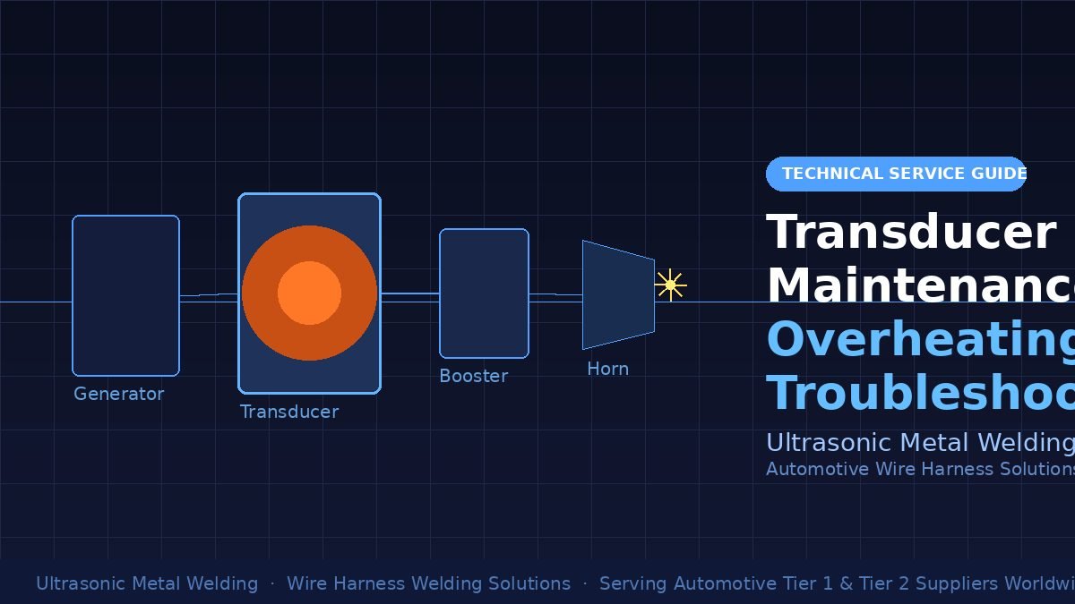
In automotive wire harness production, a single transducer failure can halt an entire assembly line. This guide consolidates what our field engineers have learned from servicing systems across North America and Europe — so your team can catch problems early, not after the damage is done.
Why the transducer deserves more attention than it usually gets
Most downtime incidents we’re called in to investigate trace back not to the generator or the fixture — but to a transducer that was running degraded for weeks before it failed. The transducer converts electrical energy into mechanical vibration at 15–40 kHz. That makes it the most mechanically stressed component in the stack, and the one most sensitive to contamination, improper torque, and thermal cycling.
Yet in many plants, transducer checks are still done reactively — after weld quality drops or the machine alarms out. The checklist below changes that.
Routine maintenance checklist (weekly / per-shift)
- Inspect the mating faces (transducer ↔ booster) for fretting marks, corrosion, or contamination. Any oxidation layer increases interface impedance and generates heat.
- Verify bolt torque with a calibrated torque wrench — do not retighten by feel. Refer to the manufacturer’s spec (typically 20–35 N·m depending on stack size).
- Check the cable connection at the generator output. Loose or corroded BNC/lemo connectors cause reflected power and premature transducer fatigue.
- Log the operating temperature at the transducer body after a standard production cycle. Baseline this number — deviations of more than 10–15 °C from baseline warrant investigation.
- Listen for changes in the acoustic signature during test welds. Rattling, irregular amplitude, or frequency drift are early indicators of a cracked piezo disc or delamination.
- Keep the transducer body free from coolant splash, flux residue, and metal chips — especially in harness welding cells where copper fines are abundant.
Field note: In high-volume automotive harness lines running 3 shifts, we recommend shifting to a bi-weekly torque check rather than monthly — thermal cycling from continuous operation accelerates bolt relaxation faster than most OEM schedules account for.
Overheating: what it looks like, and what’s actually causing it
Transducer overheating is one of the most common service calls we receive from wire harness production facilities. The symptom is usually clear — the generator triggers a thermal alarm, or the transducer body is too hot to hold. The cause is almost never the transducer itself.
| Symptom | Likely root cause | First action |
|---|---|---|
| Heat localised at the booster/transducer joint | Insufficient torque or contaminated mating face | Disassemble, clean with isopropyl alcohol, retorque to spec |
| Uniform body heat with stable amplitude | Extended duty cycle beyond design rating | Review weld time / rest time ratio; add inter-weld dwell |
| Heat with amplitude instability or frequency drift | Cracked piezo ceramic or delamination | Full impedance sweep — replace transducer if resonance peak is flat or shifted |
| Heat with high reflected power reading at generator | Impedance mismatch — worn horn or incorrect booster ratio | Check horn condition and booster amplitude ratio against application requirements |
| Intermittent heat, worse in afternoon | Ambient temperature exceeding operating envelope, or inadequate enclosure ventilation | Verify enclosure ventilation; add directed air cooling if needed |
Impedance testing: the check most facilities skip
Visual inspection and temperature logging will catch most problems — but not internal piezo degradation. The only reliable way to detect this early is an impedance sweep (sometimes called an admittance plot or frequency sweep).
A healthy transducer produces a sharp, well-defined resonance peak. A degraded one — from cracked ceramics, delamination, or poor bonding — shows a broadened, shifted, or split peak. This test takes under three minutes with the right equipment and can predict failure weeks before it happens.
Recommendation: Run an impedance sweep on every transducer at installation, and log the result. Re-run quarterly, or any time weld quality metrics (tensile pull-force, cross-section review) show unexplained drift. That baseline is your most valuable diagnostic reference.
What to send us when you need remote support
When customers contact our service team with a transducer issue, these four data points let us diagnose remotely in most cases — saving days of waiting for an on-site visit:
- Generator error log export (full, not just the last alarm)
- Impedance sweep chart, or at minimum the displayed resonant frequency and phase angle
- Weld parameter file (energy, amplitude %, weld time, trigger force)
- Photos of the mating faces and cable connections
When replacement is the right call
Transducers are durable — a well-maintained unit in a harness welding application should last 3–5 years under normal production loads. But delaying replacement past the point of degradation is almost always more expensive than the transducer itself: scrap, rework, and unplanned downtime cost far more.
Replace when: the impedance sweep shows significant peak degradation, the operating temperature is consistently 20 °C or more above baseline despite correct torque and clean interfaces, or weld quality cannot be stabilised within normal parameter ranges.
Do not attempt to re-bond delaminated piezo ceramics in the field, or run a suspected cracked transducer at reduced amplitude to “extend its life.” Both approaches risk sudden failure mid-weld — and in a harness welding cell, that typically means a ruined fixture and potentially damaged tooling.
Questions about your specific transducer model or welding application? Our engineering team supports automotive Tier 1 and Tier 2 suppliers across North America, Europe, and Asia. Contact us →